Testing Vertical Accuracy
Posted on
Ensuring Your Data Will Serve Your Needs
To ensure our geospatial data is suitable for its intended use, Surdex performs thorough accuracy testing prior to delivery, certifying that all products meet the project’s accuracy requirements. This is a critical step because if for any reason the data does not meet the appropriate accuracy requirements, any analysis performed with this data will not produce reliable results, which could cause serious problems down the line. Vertical accuracy testing is an essential step for any of our projects involving lidar or other elevation data and/or derivative products such as Digital Surface Models (DSMs) or contours. Some clients prefer to verify the product accuracy through an additional round of independent testing; the procedures described in this document can help guide you through that process.
What accuracy requirements should I use?
Ideally, you should determine the appropriate accuracy standards before issuing an RFP or signing a contract so that your geospatial data provider can design the data acquisition/production plan around these standards. The American Society for Photogrammetry and Remote Sensing (ASPRS) has a document titled ASPRS Positional Accuracy Standards for Digital Geospatial Data.* These standards are widely accepted and used in the geospatial industry; Surdex uses these standards (unless clients specify otherwise), and we recommend our clients use them as well. The USGS Lidar Base Specification** is another great resource for lidar accuracy requirements. Table 7.2 in the ASPRS document is a great starting point to help you determine the appropriate accuracy standards for your dataset based on the desired vertical accuracy class.
What is the process for vertical accuracy testing?
For vertical accuracy testing, the ASPRS standards offer a recommended number of quality control (QC) points based on the size of the project area. The QC points are broken down into non-vegetated vertical accuracy (NVA) and vegetated vertical accuracy (VVA) check points. Your geospatial data provider should review these recommendations with you to determine the proper number of points for your project based on analysis needs and budgetary constraints.
Testing vertical accuracy involves three major steps:
1. Planning and selecting the field survey points
2. Performing a field survey of the QC points and
3. An in-office analysis comparing the elevation of each QC point in the dataset under review (e.g., lidar point cloud) to their elevation in the field survey.
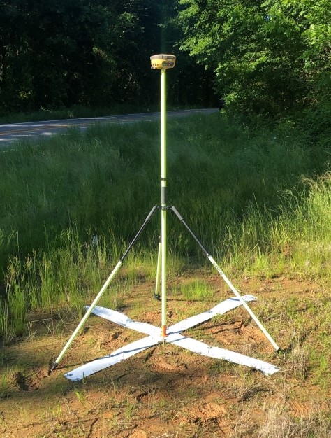
The location of the survey points should in general be evenly distributed throughout the project area and represent good locations for measurement. Access and vegetation will play into this selection process and result in the movement of some points to more desirable locations. Field survey data should include the XY coordinate location and elevation of each QC point, as well as ground photos which provide detail on the ground surface material, slope, and any nearby obstructions. The additional information provided by ground photos helps with assessing interpolation accuracy.
The check point survey needs to be of a higher accuracy than the geospatial product to ensure it truly tests the accuracy of the product; the ASPRS guidelines indicate that the check point survey should be at least three times more accurate than the required accuracy of the geospatial product. To assess the accuracy of an elevation product with a 10 cm root mean square error z (RMSEz) accuracy, the check point survey would have to be accurate to approximately 3.3 cm RMSEz.
There are many different software packages that can be used for vertical accuracy testing; Surdex uses Merrick’s MARS® QC Module for this task. The XY coordinates for the field survey points are entered into the program, then the program interpolates the elevation for the same XY location in the raw or derived elevation dataset under review. Elevations of the QC points derived from the geospatial product are then compared to the original field survey elevations, and a statistical summary is generated from the discrepancies measured between the two datasets. This analysis follows the National Standard for Spatial Data Accuracy guidelines for geospatial data accuracy assessment and the ASPRS standards.
The following table presents a portion of an accuracy report for a QL2 lidar point cloud that required a 10 cm RMSEz in non-vegetated terrain, a ±19.6 cm NVA at a 95% confidence level and a ±29.4 cm VVA at a 95% confidence level. Values for errors and accuracies are provided in meters.
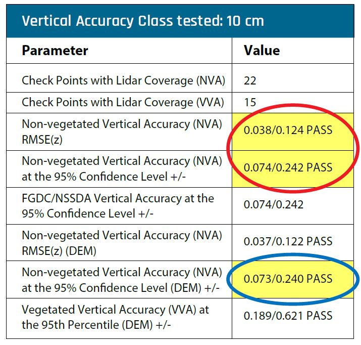
You will see in this report (in red circle) that the accuracy of the lidar data has an RMSEz of 3.8 cm in non-vegetated terrain. This is well below the 10 cm requirement. In addition, the NVA was ±7.4 cm at the 95% confidence level and the VVA was ±18.9 cm at a 95% confidence level (in blue circle), both below their requirements as well (±19.6 cm and ±29.4 cm, respectively). Therefore, we can see that the lidar data meets the desired product specifications.
With this testing completed, the metadata of this product would include the following accuracy statement: “This data set was tested to meet ASPRS Positional Accuracy Standard for Digital Geospatial Data (2014) for a 10-cm RMSEz Vertical Accuracy Class. Actual NVA accuracy was found to be RMSEz = 3.768cm, equating to +/- 7.385cm at the 95% confidence level. Actual VVA accuracy was found to be +/- 18.921cm at the 95th percentile.”
Where can I learn more or get help?
The ASPRS and USGS have a wealth of materials regarding geospatial product accuracy. If you have questions about testing accuracy to ensure your data is suitable for your work, we would be glad to help.
Download a PDF of this article on vertical accuracy for your convenience.
* ASPRS Positional Accuracy Standards for Digital Geospatial Data, https://www.asprs.org/news-resources/asprs-positional-accuracy-standards-for-digital-geospatial-data.
** USGS Lidar Base Specification https://www.usgs.gov/core-science-systems/ngp/ss/lidar-base-specification-online